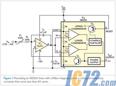
NE555定时器和Miller积分器结合组成电压到频率转换器,价格低于50美分。
1971年,Signetics——Philips的前身——生产了NE555定时器,目前制造商每年仍生产超过十亿件产品。通过给NE555增加一些器件,可以构造价格低于50美分的简单电压频率转换器。电路包括NE555定时器和基于TL071的Miller积分器(图1)。应用中输入电压为0到-10V,产生0到1000Hz的输出频率范围。C1的电流为输入电压的函数:IC=–VIN/(P1+R1)。

C1的电压达到VCC的2/3时,定时器的内部放电晶体管打开,C1的电压回到VCC的1/3,比较器的低阈值。到电压的1/3处,放电晶体管关闭,C1再次开始充电。C1充电时,NE555的输出为高,而C1放电时,NE555的输出为低。输入电压和C1充电时间的乘积为常数。因为放电时间小于充电时间,下面的公式计算了输出频率fOUT~VIN/(P1+R1)×C1×1/3VCC。
P1校准了输出频率和输入电压的关系。因为放电时间约为30µs,电压频率转换的精度随频率的增加而降低。如果设定100Hz为-1V,1000Hz为-10V,转换范围的误差为0.3到3%。如果使用P1校准输入电压范围中点-5V的输出频率,那么整个范围内的转换误差小于1.3%。为改进性能,C1应该具有低耗散的特点。如果R1具有低温度系数,P1为多匝金属陶瓷电位计的话,可以减少温度影响。
英文原文:
NE555 timer sparks low-cost voltage-to-frequency converter
The combination of an NE555 timer and a Miller integrator yields a voltage-to-frequency converter that costs less than 50 cents.
Gyula Diószegi and János Nagy, Divelex Ltd, Budapest, Hungary; Edited by Charles H Small and Fran Granville -- EDN, 2/21/2008
In 1971, Signetics—later Philips—introduced the NE555 timer, and manufacturers are still producing more than 1 billion of them a year. By adding a few components to the NE555, you can build a simple voltage-to-frequency converter for less than 50 cents. The circuit contains a Miller integrator based on a TL071 along with an NE555 timer (Figure 1). The input voltage in this application ranges from 0 to –10V, yielding an output-frequency range of 0 to 1000 Hz. The current of C1 is the function of input voltage: IC=–VIN/(P1+R1).
As the voltage on C1 reaches two-thirds of VCC, the 555’s internal discharge transistor opens, and the voltage on C1 returns to one-third the voltage of VCC, the lower comparator threshold. At one-third this voltage, the discharge transistor switches off, and C1 again starts charging. The NE555’s output is high while C1 is charging and low while C1 is discharging. The product of the input voltage and the charging time of C1 is constant. Because the discharge time is shorter than the charging time, the following equation results for the output frequency: fOUT~VIN/(P1+R1)×C1×1/3VCC.
P1 calibrates the relationship between the output frequency and the input voltage. Because the discharge interval is approximately 30 µsec, the accuracy of the voltage-to-frequency conversion decreases as the frequency increases. If you assign 100 Hz to –1V and 1000 Hz to –10V, the error of conversion ranges from 0.3 to 3%. If you use P1 to calibrate the output frequency in the middle of the input -voltage range at –5V, then the conversion error will be less than 1.3% over the entire range. To improve peRFormance, C1 should have a low dissipation factor. You can diminish temperature dependence if R1 has a low temperature coefficient and P1 is a multiturn, ceramic-metal potentiometer. |